
Kinematic solution with RTKPOST
RTKPOST is the GUI tool in RTKLIB to calculate position solutions. Most of the time I find the CUI version (RNX2RTKP) better fits my needs, but just to check everything is working, it is probably easier to use RTKPOST the first time.
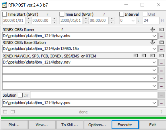
For a demonstration of using RTKPOST to find a kinematic position solution, I will use the ZDV1 (COREX station data) for base station data and the “EBAY” (Ublox M8N receiver data) for rover data. Zipped versions of this data is available here. (Update 1/24/20: This data is no longer available, but similar data can be downloaded from here.) Since the exact location of ZDV1 is known and is in the observation file header, the kinematic solution will give us an absolute position by solving for the relative distance between the rover and the base, and then adding that to the base location. I set up the GUI inputs as shown below to point the program to the correct observation and navigation files. If you use my data, be sure to change the paths to match where you saved the data to.
For this first run, to keep things as simple as possible, we will make just two changes from the default setup. Use the “Options” button to get to the options menu. Under the “Setting 1” tab, change “Positioning mode” from “Single” to “Kinematic”. This will give us a differential solution using carrier phase info instead of an absolute solution using only pseudorange. Next, under the “Positions” tab, change the first field under “Base Station” from “Lat/Lon/Height” to RINEX Header Position. This will tell RTKPOST to get the base station location from the header of the observation file.
While you are in the options menu, click the “Save” button, and save the options setup to a location you will remember later. We will use this file as the configuration input file for the CUI version. Then click OK to exit the Options menu.
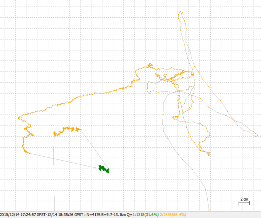
Click the “Execute” button to calculate position and then “Plot” to see the solution. Select “Gnd Trk” and zoom in and it should look like this. The two rectangles are parking lots. The yellow represents a float solution, the green a fixed solution. The fact that we were able to get a fixed solution at least part of the time is a sign things are working reasonably well.

Zooming into the initial time period when the car was stationary we see the plot below. Since the receiver is not moving during this time, any movement in the solution represents error. During the initial convergence of the kalman filter we see quite a lot of error, but once it does converge, we do get a fixed solution for 5 of the 20 minutes which appears as green in the plot below. During this time you can see the error is roughly +/- 1cm in the xy direction which again is a good sign things are working.
Note about restoring RTKPOST default options: There is no button in RTKPOST to reset the options to defaults and it remembers the options from the previous session when restarted, so there is no obvious way to put it back to defaults. The best way I have found to do this is to delete the “rtkpost.ini” file saved in the rtklib\bin folder before starting RTKPOST.

Hi everyone
I’m a new user of RTKLIB
I need to do PPK processing on my drone images
But after installing it I can’t import RINEX OBS files of the base station cause the function is not avtivated
I don’t know why
I even changed the version, but same issue.
Thanks for help !
LikeLiked by 1 person
Hi Chris. You can only specify a base observation file in RTKLIB post processing if you have selected a PPK solution mode, either “Static” or “Kinematic”. All other solution modes use just a single receiver.
LikeLike
Does anybody know how to interpret the output of the tropospheric parameters?
Why are there 2 separate values for rover and base in RTK processing? Usually the output should only be a differential tropospheric parameter between the two. How can I get this differential value?
There seems nothing to be documented on this.
LikeLike
Hi Tropguy. I haven’t used the troposphere output myself, but from the RTKLIB manual, it appears that one value is from the float solution and the other is from the fixed solution. Here’s the output format:
$TROP,week,tow,stat,rcv,ztd,ztdf
week/tow : gps week no/time of week (s)
stat : solution status
rcv : receiver (1:rover,2:base station)
ztd : zenith total delay (m) float
ztdf : zenith total delay (m) fixed
LikeLike
Thank you for answering. I saw this as well. In total, there are 4 output values (fixed and float for rover and base). But in differential positioning, I would expect a differential value, the tropospheric delay difference between base and rover and not two separate values. Forming the difference or sum of two values (rover and base) doesn’t give the desired results either. The absolute values for the individual stations (rover and base) don’t seem to be in the correct order of magnitude either (which they obviously can’t be when we are doing double difference observations).
LikeLike
Hi mate, the updated sample data is currently just a blank page. Cheers
LikeLike
Hi Dazonic. Thanks! – I’ve just fixed it.
LikeLike
Hello @rtklibexplorer
I am processing kinematic analyses using rktpost. I would like to do Troposphere correction in my analyses.
I am wondering if you could tell me how to input the meteorological data, temperature, humidity, atmospheric pressure, to rtkpost to do the correction.
Thank you very much for you consideration.
Kien
LikeLike
Hi Nguyen. RTKLIB has the capability to input ZPD files with site specific tropospheric delays and gradients for PPP solutions but this doesn’t sound like exactly what you want. You may find it useful to read the RTKLIB user manual Appendix E.5 for more info about how RTKLIB models the troposphere.
LikeLike
Hello @rtklibexplorer
thank uu again for your answer,
For the transformation of the coordinates, I calculate the points of trajectography, ie more than 29000 points, and from what you told me, I understood that RTKLIB gives that the coordinates in WGS84, the site That you gave me it makes that transformation of a single point .. so there is no way to have a transformation of a file points?
For the question of FORWARD / REVERSE, please, if there is a discriptive algorithm of this method and how does it work without using the inertial data ??
LikeLike
Hi Saidgnss. I don’t know of any easy way to convert a whole file of coordinates. However, if you convert your base station to the desired coordinate system and your baselines are reasonably short, I believe the resulting rover measurements, which are relative to the base, will effectively be in the desired coordinate system with only very small errors.
A description of the forward and reverse solution modes used by RTKLIB can be found in the RTKLIB 2.4.2 user manual in Appendix E
LikeLike
Hi ,I want to know how long does it take to converge? Thanks! Looking forward to your reply.
LikeLike
Hi Shigeng. Initial convergence time to first fix will vary significantly depending on configuration. If I am using two M8T receivers with GPS,GLONASS, SBAS, and Galileo enabled with good sky views and a short baseline, 1-3 minutes is typical, but under poor conditions 10-20 minutes might not be uncommon, and in very poor conditions, the solution will often never converge to a fix.
LikeLike
Excellent blog, rtklibexplorer! I’ve been tying to do something similar and am glad to have found someone in the same boat, as it were. Unfortunately, I haven’t been able to get my setup to work yet. I am using the same eBay module as you (mine includes the magnetometer) and the stock antenna. I have the module working with rtknavi and am streaming base station data from a local (~10km away) NTRIP server. I have a clear view of the sky with no tall buildings or trees and am holding the rover in a fixed location. The problem is the RTK solution is almost always float and is not precise at all. Only rarely does it enter the fix state and only very briefly. I have tried a few other base stations, with the same results. My instinct is to blame the antenna, but the reported SNRs are in the mid-high 40s, which I understand to be good enough. Is there something obvious I’m missing?
LikeLike
Hi Janame. Glad you enjoyed the blog! Given your conditions you should be getting good fixes. Are you using a decent ground plane for the antenna? Ublox recommends a 50 to 75 mm square centimeter ground plane, but larger should be OK too. There are more good suggestions for improving your data collection environment in this document from Ublox.
If that doesn’t help I would suggest downloading the code/configuration files/data from my Github repository and running your data with my code/configuration and vice-versa to determine if the problem is in the data, code, or input configuration.
LikeLike
I made some test with my current setup: 2 Tallysman TW3040 connected to the M8T base receiver (1hz) and to the LEA6T for rover position set at 5 Hz output rate.
I found some improvements changing the errratio1 from 100 to 300 (even if I don’t completely understand the meaning of this parameter)
While I found very bad results adding rows:”pos2-arthres1 =0.9999; pos2-arthres2=0.25; pos2-arthres3 =0.1;
pos2-arthres4 =0.05; since my starting conf file didn’t have them. Very short fix time and very poor ratio value.
Even for these parameters I don’t know exactly what are affecting. Have you some info about this?
In the next days I will apply changes to fix the “pos2-arlockcount” bug then recompile for the Raspberry model 2.
From my experience I noticed that better results exist when low number of satellites are taking into account for ambiguity resolution and then fix-and-hold. Around 6 satellites (good results also with 7 or 8 max).
Instead to cut down satellites with SNRmask filter could it be possible to process only the best 6-7 satellites with best SNR? May I’m wrong?
I’m an electronic engineer but I’m not an expert about GNSS.
LikeLike
Hi generaldin. Eratio1 is a user estimate of the ratio of standard deviations of pseudorange errors to carrier‐phase errors. My understanding is that increasing this number causes RTKLIB to increase emphasis on the carrier phase measurements over the pseudorange measurements in its updates to the kalman filter.
arthres1-5 were new with the default config file for 2.4.3 release. None of them are used by the code however and it should not make any difference what these values are set to.
In general, the more high quality satellite signals used for ambiguity resolution the better since it increases the confidence in the solution, but I agree that excluding lower quality signals can be important since a single bad satellite can prevent a fix no matter how many good satellites you have. The SNRmask filter can help with this with the existing code.
I have also had some success with experimental code I have been playing with that qualifies each new satellite before adding it to the fixed solution set. Satellites are not qualified if they break or severely degrade the AR ratio and are re-qualified at specified intervals to catch satellites that have degraded. I hope to write a post on this once I’ve had a little more time to work out the details.
LikeLike
The Google Drive link: https://drive.google.com/drive/u/0/folders/0B8-y6z0J1OeZflV0NkR2NDZzbGJJMEZMazVVenJxM0NmZkJ2MDlYSlhVLWRMcU1JSURURmc is not working, at least for me
LikeLike
Sorry … I don’t know why the link isn’t working, it’s supposed to be shared for anyone. You can find all the raw data at my github page in the demo1/data in the demo1/data/demo1 folder. The complete .conf config file is there as well.
LikeLike
Thank you rtklibexplorer. I’ll check your .conf file with my own version.
LikeLike
Hello @rtklibexplorer,
i’m new in RTKLIB, I calculated the trajectography of an embedded 3D scanner, I used several software in order to compare the results of calculations for each software, I started with two commercial software, after I calculated by RTKLIB, but j I noticed that we can not know the antenna heights, nor the type of antenna (because it requires delta (e / n / h), and after the calculations I had 1cm in Y, and 8- 9 cm in X, Z? I do not understand why these differences? Please help to fix this problem..
LikeLike
Hi Saidgnss. Exact matches to an absolute point or solution are tricky because of different coordinate systems and antenna offsets. I do not have access to a geodetic grade receiver and also do not have PCV to ARP calibration values for most of my antennas so I have focused more on verifying relative measurements and not absolute measurements.
LikeLiked by 1 person
Hello @rtklibexplorer
Thank you for the repense,
I calculate the trajectogram of a scanner in PPK mode (relative mode) with an embedded GPS and a base station 1km of project,
1 / in RTKLIB I had the same results either with the braodcaste or with the precise ephemerides (if we use this equation of [(or error + datum shift error) * (baseline / dist to satellites) A baseline 50km one will see 5mm of error)
2 / for antennas: when I used Delta (e / n / h) = 0.00 / 0.00 / 1.47 for the ROVER and 0.00 / 0.00 / 1.28 for the base station, then I had results close to My calculations of commercial software (1cm in E, 8mm in N, and 1 cm in Z)
Knowing that I noticed that: when I change the method of correction iono and tropo its not changing the results? !!!!
3 / the coordinates are still in WGS84 there is no average to make them out in RGF93 ??
4 / if you can please explain to me how it uses the forward / reverse method (KALMAN filtering) without the inertial data?
I wait for your repentance with patience
thank you
LikeLike
Hi Saidgnss. I use this site for converting from one coordinate system to another but I don’t know if it includes RGF93.
With only a 1 km baseline I would not expect significant changes when using precise or broadcast ephemerides or by changing the tropo or iono correction since with such a short baseline, the errors will mostly cancel out between rover and base and will not need correction.
The forward/reverse processing modes in RTKLIB only refer to which direction the kalman filter processes the measurement data in post-processing mode (begin->end or end->begin), so no need for inertial data in either direction.
LikeLiked by 1 person