
In my last post I introduced a new more challenging data set with a higher number of cycle slips than in previous sets. Even after improving the RTKLIB code to better handle missing data samples, there are still a large number of points in the solution with only a float status (yellow in the plot). In addition, the last 15 minutes appears to have at least a meter of error in the vertical axis since the data was taken in a series of loops and the vertical measurements should be the same as earlier loops.
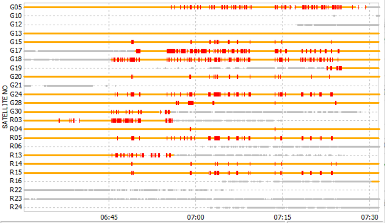
By plotting the observations of the rover, we can see that there are many cycle-slips on a large number of the satellites. This is the primary cause of the poor solution. Here’s the rover observations with a 15 degree elevation mask.
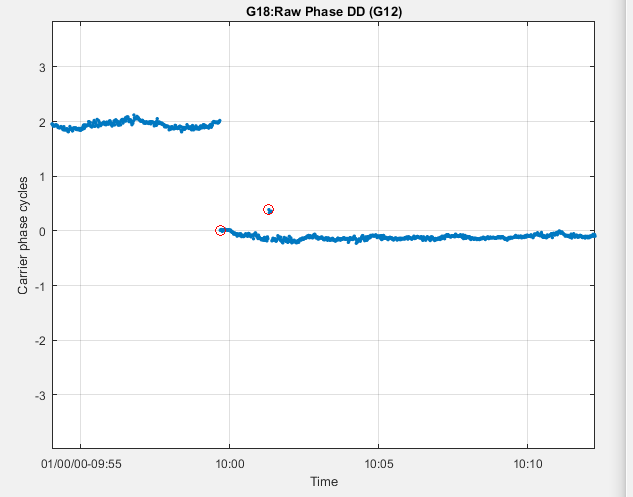
In order to improve this solution, we are going to have to take a closer look at the cycle slips. The first thing I noticed when examining a few of these cycle slips is that there are a lot of half cycle errors in the carrier-phase measurements following a reported cycle slip. This is true whether or not an actual cycle slip occurred. I had seen this earlier as well when doing an exercise of looking at the double differences. Here’s a plot from that previous post showing what I am talking about. The second red circle contains a number of samples all in error by almost exactly one half cycle.
Let’s go back to the raw ublox data before it is converted into RINEX format to see if that can shed any light on what is going on. To see the raw unconverted ublox data I enabled the trace option when running convbin by adding “-trace” to the command line. I also had to change an “if #0” in the code in the decode_trkmeas() function in ublox.c to an “if #1” to output the full debug information. Below on the top is the rover observations zoomed into a time period around 6:45:27.0 and below is the raw ublox data for that sample.


The flag byte is what we are interested in. Since the M8N does not officially support raw output, there is no documentation for this data byte. From the existing ublox.c code though we can see how RTKLIB is using it. It is interpreting bit 5 (0x20) as phase lock and bit 6 (0x40) as the half cycle bit. When the half cycle bit is set, one half cycle is added to the carrier-phase measurement. The other 6 bits are being ignored.
Looking at the documentation for the M8T which does officially support raw data provides a hint as to what might be going on. In the description of the RAWX command one of the bits in the trkStat byte is used to indicate whether the half cycle bit is valid or not. Since the M8N and the M8T share the same core, it would be reasonable to assume there was an equivalent bit in the M8N.
We know from the data that the half cycle errors occur shortly after a reported cycle slip so let’s look at those satellites. From the observation plot we can see that in this case satellites G30, R03, R22, and R23 all have reported cycle slips in the last few seconds before the sample we have raw data for (6:45:27.0). If we look at the flag byte for those satellites, we can see that bit 7 (0x80) is clear for all four satellites. It is set for all the other satellites except G21 which has no valid data and I120 which is the SBAS satellite. Each line in the raw data is one satellite, “sys” is the system (0=GPS,1=SBAS,6=GLO) and “prn” is the satellite number. We can also see that when bit 7 is clear, the half cycle bit (0x40) is never set which would also be consistent with bit 7 being the “half cycle valid” flag.
I added the following line of code to the decode_trkmeas() function in ublox.c to update the observation with the half cycle valid status in the same way it is done for the M8T. RTKLIB refers to this bit as the “Parity Unknown” bit but in a comment in the RTKPLOT part of the manual explains that this mean the half‐cycle ambiguities in carrier‐phase are not resolved.
raw->obs.data[n].LLI[0]|=flag&0x80?0:2; /* half cycle valid */
I then reran the conversion using the convbin raw data conversion CUI. Plotting the updated observation data using RTKPLOT with the “Parity Unknown” option set to “ON” gave the following result:
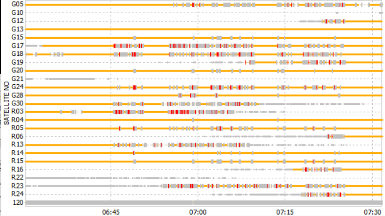
The gray ticks indicate unknown parity (i.e. half cycle invalid). Unfortunately the “unknown parity” ticks seem to take precedence over the “cycle slip” ticks, so any sample that has both shows up as “unknown parity”. This is why there seems to be less cycle slips in this plot than the original plot above.
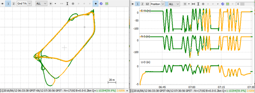
So, let’s rerun the solution on the improved observation data using the same configuration settings as previously. The result is plotted below.

This looks a lot better. Not only do we see a lot more fixes, but the obvious vertical errors between 7:15 and 7:30 have gone away. The two yellow sections in the ground track plot on the left align with the two locations where the car went directly underneath overhanging branches so it is not surprising that those spots are going to be more difficult to maintain fixes for.
There may be more opportunity for improvement here if we can figure out how to take better advantage of the half cycle status. The current RTKLIB code simply resets the phase bias estimate for that satellite every time this bit changes state.
I have uploaded this change to the demo4_b12 branch in my GitHub repository. I have also posted the modified rtkconv executable here.
The reason that I posted rtkconv (the GUI version) instead of convbin (the CUI version) is that I am now able to build the GUIs with my new Embarcadero compiler and because I have found that convbin does not seem to work for the newer (3.xx) formats of RINEX. I prefer the newer formats because they are easier to parse.

Hello RTKlibExplorer,
The hands-on solution provided in your article are very helpful to me. I’m using your solution to build my RTKlib base. I have some doubt/queries related to RTKlib and I have listed them below. It would be very helpful if you can provide some inputs. I’m using RTKlib 2.4.3 Emlid b33.
Is it consistent that there will be half-cycle error following a cycle slip? I have collected GNSS data and found that there are no half-cycle error after a cycle slip. You can refer the data: https://drive.google.com/drive/folders/1vEL5Z9_-vULipgb7VOpyraYwZVAobmAy?usp=sharing
In https://github.com/tomojitakasu/RTKLIB/blob/master/src/rcv/ublox.c , decode_rxmrawx(raw_t *raw) parse the SNR value and then multiply it by 4. Why not the raw data value is used as it is?
What is -TADJ=tint (Adjust time tags to multiples of tint in sec) option for Ublox ?
What is the significance of -STD_SLIP option and how to use it in RTKlib ?
How post processing software play a role in improving the GNSS data ?
Can you provide the format in which RINEX opt are mentioned in RTKPlot’s setting ?
All the questions listed above are not related to this particular article. If possible please your contact details so that we can directly communicate over it.
Thank you
LikeLike
Hi Krishna. Here’s some answers to your questions, they apply specifically to the demo5 version of RTKLIB but the Emlid code should be similar.
Is it consistent that there will be a half-cycle error following a cycle slip? I have collected GNSS data and found that there are no half-cycle errors after a cycle slip. You can refer to the data: https://drive.google.com/drive/folders/1vEL5Z9_-vULipgb7VOpyraYwZVAobmAy?usp=sharing
Not all cycle slips will be followed by a half cycle ambiguity. The half cycle ambiguities indicate that the receiver has not fully resolved the carrier phase. This may or may not happen before the next output sample. However, at least for u-blox receivers, RTKLIB will insert a cycle slip into the raw data each time the half cycle ambiguity changes state.
In https://github.com/tomojitakasu/RTKLIB/blob/master/src/rcv/ublox.c , decode_rxmrawx(raw_t *raw) parse the SNR value and then multiply it by 4. Why not the raw data value being used as it is?
This is because RTKLIB stores the SNR values in an integer variable. Multiplying by 4 increases the resolution of the variable to 0.25. Note that in the b34 code, this has been changed from multiplying by 4 to dividing by SNR_UNIT which is currently set to 0.001.
What is -TADJ=tint (Adjust time tags to multiples of tint in sec) option for Ublox ?
What is the significance of the -STD_SLIP option and how to use it in RTKlib ?
There are brief descriptions of these and all other receiver options in the Demo5 RTKLIB user manual and more complete descriptions in this post.
How post processing software plays a role in improving the GNSS data ?
Not sure I understand this question. Post-processing can improve the solution over real-time, mostly because the raw data can be processed in both directions (forward and backward) and the results combined into a single solution.
Can you provide the format in which RINEX opt must be provided in RTKPlot’s setting ?
The receiver options are listed by receiver type in appendix D.5 of the Demo5 RTKLIB user manual.
Hope that helps!
LikeLike
I have been using your demo5 code quite a bit, learning rtk from it :), one of the problems with my rover and base station data are the cycle slips. I gone back in and excluded the satellites with a lot of cycle slips and the solution improved dramatically. What I would like to know is if there is a way to do this automatically in the set-up (options or config file)? If not is there a way to modify the code in rtknavi to do this, say create a criteria that if you get x number of slips in y seconds the satellite should be excluded?
Thanks Mike
LikeLike
Hi Mike. There are several config options in RTKLIB that will help filter out the effect of cycle slips on the solution. Cycle slips will tend to occur on low elevation and low SNR satellites and there are masks to exclude measurements from satellites below a given elevation or measurements below a specified SNR. There are also a couple of settings that affect how long it takes a satellite to be added back into the ambiguity resolution after it has had a cycle slip. Enabling the “pos2-arfilter” option will prevent a satellite from being added back into the ambiguity resolution after a cycle slip until it’s ambiguity can be resolved. Setting the “pos2-aroutcnt config option to a non-zero value will delay satellites from being added back for that number of samples.
In the case of a moving rover, most or all satellites will tend to have cycle slips at one point or another as the rover moves and it’s sky view changes, so excluding specific satellites for the whole solution is usually not the best strategy.
LikeLike
Thanks for the explanation. I have been reading the posts on the cycle slips and the ar filter but was a bit confused. Your explanation here makes sense and will try to implement. What I am really trying to do is keep the base station fixed and connected directly to my laptop and I have the rover portion mounted on a rc car moving around the yard as a test vehicle before I put it into my robot for waypoint navigation.
I took your advice in the previous post about unchecking the time block to run back the nav solution in rtknavi but ran into another issue in that it does not play back the entire run? It tends to stop updating at some point. Don’t know why so I just use rtkpost which works.
ps. Have you ever thought about writing a book on this.
Thanks again
Mike
LikeLike
Hi Mike. I haven’t seen the issue you describe in RTKNAVI but I’ll keep an eye out for it. I think if I tried to write a book about this it would be out of date long before I finished it! I would like to organize the material better though and hope to reformat more of the material and move it over to the rtkexplorer.com website.
LikeLike
Hey,
I just stumble over and over the Parity Unknown flag again and again. I think I just do not understand the explanation of the RTKLIB manual:
“parity unknown flags (That mean the half‐cycle ambiguities in carrier‐phase are not resolved). ”
What exactely does that mean? Is that actually the same as the carrier phase valid bit (you described this value in another post).
What are half-cycle ambiguities? Cause I thought this is actually about carrier phase signals from the satellites – and there is no ambiguity solved yet… – Does the partiy unknown flag indicate that a carrier-phase signal is kind of damaged?
…sorry would be so happy for a more precise explanation of the parity unknown flag and from which value(of a GPS receiver) this is determined.
Best
u-Bloxer
LikeLike
Hi u-Bloxer. I haven’t completely figured this out either but this is my understanding:
– When the phase lock loop in the receiver first acquires phase lock to the carrier signal there is a possibility that it is actually 180 degrees out of phase. This means there is a half cycle uncertainty in the answer. During this time, the carrier phase valid bit will be set, but the half-cycle valid bit will not be set to indicate the uncertainty. Once the 180 degree phase uncertainty is resolved, the half-cycle valid bit will be set. I believe the phase-lock loop uncertainty is at least in part due to the additional modulation on the carrier phase that comes from the navigation information. I don’t know why RTKLIB uses the term “parity unknown” to describe this flag, maybe there is a historical reason. I also don’t know to what extent this applies to all GPS receivers and how much this is specific to the Ublox receievers.
Here’s a bit more info from a paper on cycle slip detection
“there may be an additional half-cycle ambiguity due to the navigation message modulated on the
signal. As the message is not known beforehand, it cannot be removed to obtain a clean sinusoidal carrier wave to track. For this reason, carrier tracking loops are sometimes constructed as Costas loops which are insensitive to 180◦ phase shifts caused by, e.g., navigation data bit changes. Such a loop does not know if it is tracking the carrier correctly or off by 180 degrees”
Maybe someone more knowledgeable with receiver design can add to this explanation.
LikeLike
Great work!
One question on the convbin vs rtkconv: I get complete identical obs messages when using either CUI or GUI from RTKLIB 2.4.2. Unfortunatly I can’t use your GUI’s (or the GUIs from the official 2.4.4 dev branch) because I use wine and get and error about SHCORE.dll missing).
So coulf you specify the problems you have with convbin?
LikeLike
Hi Johannes. I found that convbin worked fine if I specify a 2.xx version of RINEX output using the -v option or let it use the default which is 2.11. If I specify any version of RINEX 3.xx on the command line, then convbin crashes. I just verified that the latest 2.4.3 release code (b19) has the same problem. For most purposes, there is nothing wrong with using the 2.xx version, I just prefer the 3.xx output because it is easier to parse with something like matlab or python.
LikeLike
Have you try to fix M8N glonass ambiguity, and how to deal with the receiver biases described in this http://gpspp.sakura.ne.jp/paper2005/gpssymp_2014_ttaka.pdf
LikeLike
Hi Wil. I have extended fix-and-hold to deal with the GLONASS receiver biases but this is only a partial solution since it still requires the acquire to be done with only the GPS satellites. See this post for the details of what I did.
LikeLike
I have post-processed some of my static and kinematic files using your Demo4 software. It appears to be good improvement. Jumps in static surveys seem to be in the mm range for short baseline static surveys in near building – pine tree environment. I am too impatient to do a recommended 24 hour static survey to establish a precise base marker, but it looks like I am ready to go for it.
I don’t fully understand the stat-prnaccelh and stat-prnaccelv modes. There seems to be little about these on the internet. I did notice that in the kinematic modes that they appears to smooth the data by acting as smoothing filtering on the solution. Lowering the value too much causes overshoot in sharp turns, so value appears to have to be matched to the survey mode to the maximum acceleration of the carrier.
Of course, in UAV mapping, with a good base & sky view, you probably wouldn’t want any time delay, so this would most likely be of help in poor environments. I noticed some improvements walking 2 meters away from a 2 story building with pine trees blocking sky views periodically.
Again, appreciate your insights & improvements. Hopefully, this continues to work without unforeseen problems.
(using GPS + Glonass+ Demo4-RTKPOST M8T?Reach)
LikeLike
Hi Richard. Glad to hear the demo4 code is working for you, it’s nice to know it helps on other setups than just mine.
The config parameters prnaccelh and prnaccelv are used by the kalman filter if receiver dynamics are enabled. They describe how quickly the rover (or more precisely, the rover antenna) is expected to accelerate in the horizontal and vertical directions. Specifically, they are standard deviations of the accelerations. The optimal value for these settings will vary depending on the specifics of the rover. The default settings of 10,10 are very high because they are chosen without any knowledge of the rover and it is better to under-constrain than over-constrain the model.
A simple way to choose more optimal values for these two parameters is be to run a solution with the default prnaccelh and prnaccelv values, plot the acceleration with RTKPLOT, then eyeball the peaks of the data points with fixes, ignoring the very highest peaks and divide by three (remember from basic statistics that for a normal distribution, 3 sigma is equal to 99.7% of the population). This should be good enough, especially if you estimate a little high, but if you want a more optimal estimate you can parse the acceleration data from the solution status file and calculate the standard deviations directly. If you do this, you should ignore data where the rover is stationary.
For my demo4 data example of a car driving fairly slowly in circles on a dirt road, I calculated values of roughly 0.5 for prnaccelh and 0.25 for prnaccelv. You might expect prnaccelv to be closer to zero since the primary motion of the car is almost entirely in the horizontal directions. However, the accelerations include higher frequencies that might come from things like the car hitting a pothole or from engine vibration. These will have significant vertical components and drive the vertical value closer to the horizontal value.
LikeLike
Hi, your blog is fantastic. Thank you for sharing.
LikeLike
I can confirm that I have also used bit 7 to determine half-wave ambiguity status on parts without official raw data.
I’m not familiar with any parity flag in the Rinex LLI definition, but navigation message parity information is used to resolve the half wave ambiguity, so I suppose these are the same thing in RTKLib.
Regarding the LLI bits, Rinex v3.02 states: “Bit 1 set : Half-cycle ambiguity/slip possible. Software not capable of handling half cycles should skip this observation. Valid for the current epoch only. ” In Rinex v2, this was handled with the same LLI bit and an alternative wavelength factor specified in the header.
This “alternative wavelength” approach is often how half-wave ambiguous measurements are handled in processing – still as integer multiples, but of a wavelength half as large.
LikeLike
Hi James. Thanks for the confirmation and the clarification on the Rinex bits. After reading your comment I went back to the RTKLIB manual and found a comment in the RTKPLOT section that confirms that “parity unknown” means that “the half‐cycle ambiguities in carrier‐phase are not resolved”. I have updated the post to correct this.
LikeLike