
To get a high precision fixed solution in RTKLIB we need to resolve the integer ambiguities that come from the carrier phase measurements. Resolving the integer ambiguities for the GLONASS satellites is more challenging than resolving them for the other constellations. This is because, unlike the other constellations, the GLONASS satellites all transmit on slightly different frequencies. This introduces an additional bias error in the receiver hardware.
These hardware biases are constant, generally the same for all receivers from the same manufacturer, are proportional to carrier frequency and are similar between L1 and L2.
In the demo5 version of RTKLIB, there are four choices for how to handle GLONASS ambiguity resolution (AR). I will cover all four briefly, but then focus on the “autocal” setting which I have enhanced in the most recent version (b29c) of the demo5 code.
Off: If Glonass AR is set to “Off”, then the raw measurements from the Glonass satellites will be used for the float solution but ambiguity resolution will be done only with satellites from the other constellations. If you are not using the demo5 version of RTKLIB, this is usually your only choice when using receivers from different manufacturers for the rover and the base. However, you are giving up a significant amount of information by ignoring the GLONASS ambiguities and so I would not recommend this setting if you are using the demo5 code, unless of course your receivers don’t support the Glonass satellites.
On: If Glonass AR is set to “On” then RTKLIB will treat the Glonass ambiguities the same as the ambiguities from the other constellations and will not make any attempt to account for the additional hardware biases. Use this setting if your base and rover receivers are from the same manufacturer, since in this case, the biases will cancel and can be ignored. There are also some cases in which different manufacturers have equal or nearly equal biases as we will see later, in which case you can also use this setting. This is your best solution for dealing with Glonass ambiguities. I always try to use matched receivers for base and rover if possible.
Fix-and-Hold: This is an option I have added to the demo5 code for Glonass AR. It is an extension to the “fix-and-hold” method used for other constellations but instead of using the additional feedback to track the ambiguities, it uses it to null out the hardware biases. I recommend this setting when using the demo5 code with unmatched receivers. It takes advantage of the additional information in the Glonass ambiguites most of the time. However, fix-and-hold is not enabled until after a first fix has been achieved, and so the Glonass ambiguities are not available until then. This can mean longer time to first fix and less robustness compared to the “On” option, so don’t use this option for matched receivers.
Auto-cal: This option adds additional states to the kalman filter to estimate the receiver hardware biases as a function of carrier frequency, one state for L1, another for L2. In previous experiments I had not had any success with it. Recently, however, I discovered that if I adjusted the filter settings, it can be effective for a zero baseline case, where base and rover are both connected to the same antenna so that almost all other errors are completely cancelled. With a little more experimentation I also found that for short baselines it can also be effective if the kalman filter state is pre-set to something close to the final value before the solution is started. It will then usually converge to the correct bias value. However, there is currently no mechanism in the code to adjust any of these values, so I have not found this mode to be useful in its current implementation.
To make the auto-cal option more flexible, and hopefully more useful, I made a few modifications to it in the b29c code. I added the capability to pre-set the initial state value and also to adjust the internal filter settings, specifically the initial variance and process noise for this state. The units for the state, and hence for the initial value are in meters per frequency channel and values generally are within +/-5 cm per channel. I used some existing config parameters that are currently unused to reduce the amount of code I needed to change. Unfortunately it means that the names are not as descriptive as they could be. The new config parameters are:
pos2-arthres2 = relative GLONASS hardware bias in meters per frequency slot
pos2-arthres3 = initial variance of GLONASS hardware bias states
pos-arthres4 = process noise for GLONASS hardware bias states
Bias values have been published for some of the most popular geodetic quality receivers but are generally not available for lower-cost or less popular receivers. Here is a table of values from a paper published by Lambert Wanninger in 2011 for nine receiver manufacturers.
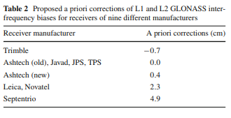
I was able to verify these results for Trimble, Leica, and Novatel, but I found a much lower value for Septentrio so I suspect the biases may have changed in their newer receivers.
To demonstrate the modified autocal option, I will start with a zero baseline case between a ComNav receiver and a Tersus receiver. It is easiest to measure the hardware biases in the zero baseline case because most other errors will cancel and the hardware biases will be the dominant error. In this case, I have significantly reduced the initial variance setting from the original value of 1.0 to 1E-7 and increased the process noise from 1E-6 to 1E-3.
I have run the solution several times with the initial bias value set to different numbers between -.05 and 0.06. Here are the results for both L1 and L2.

The convergence occurs just after first fix is achieved. If a fix is not achieved, then the state will not converge as you can see above for the 0.06 example. In this case, the initial value was too far from the correct value and prevented getting a fix. As you can see, all the other cases converged towards a single value around -.022, both for L1 and for L2.
Another way to visualize the error in the initial value is to look at the GLONASS residuals after first fix is achieved. The plot below shows the GLONASS L1 carrier phase residuals for different initial values, for 0.03 on the left, -0.05 in the middle, and what I believe is the correct value for this receiver combination of -.022 on the right.
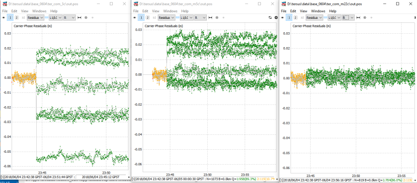
Here are the same plots for the L2 carrier phase residuals.

Through a slightly tedious process, I am fairly easily able to iterate the residuals down to near zero for different pairs of receivers in my possession. Note that this gives me the relative difference in biases for each receiver pair, and not absolute values for each receiver, unlike Wanniger’s table which is for absolute biases.
Extending the table to receivers used in nearby CORS stations is a little more challenging because the initial bias value needs to be fairly close to get a first fix and hence a convergence, but still possible if the base station is not too distant. I found data sets that included CORS data from Leica, Novatel, Trimble, and Septentrio receivers. Using the above procedure to iterate the residuals down to near zero, I was then able to extend my table and make the values absolute by choosing the unknown offset to make my bias pairs align with Wanninger’s table. This is the resulting table I created.
[Note: table updated 3/16/20:]
ComNav = 2.3 cm
Leica = 2.3 cm
Novatel = 2.3 cm
Septentrio = -0.3 cm
Spectra Physics = 0.0 cm
SwiftNav = 0.0 cm
Tersus = 0.0 cm
Topcon = 0.0 cm
Trimble = -0.7 cm
u-blox M8T = -3.2 cm
u-blox F9P = 0.0 cm
To generate an initial value for the bias state from this table for an RTKLIB solution, subtract the base station bias from the rover bias, then divide by 100 to convert from centimeters to meters. This value can then be used to set the “pos2-arthres2” config parameter in the config file. For the RTKPOST and RTKNAVI GUI option menus I have labeled this “Glo HW Bias”.
To test this code on an independent set of data after generating the table, I used a data set recently sent to me by a reader. It consists of a u-blox M8T receiver for rover and Leica receiver just a few kilometers away for base, and was collected in Europe. The rover position was static but I ran the solution in kinematic mode to make the solution a little more challenging and to make any errors in the solution more visible.
To generate the correct config value for RTKLIB I subtracted the Leica bias of 2.3 cm from the above table from the u-blox bias of -3.2 cm to get a relative bias between receivers of -5.5 cm or -0.055 m. I added “pos2-arthres2=-0.055” to the config file and then ran the solution four times, with pos2-gloarmode set to “off”,”fix-and-hold”,”autocal”, and “on”. Although I left the bias value set for all runs it is ignored unless gloarmode is set to autocal.
Here are the times to first fix, the number of satellite pairs used for the initial fix, and the number of satellite pairs being used for fix after 10 minutes.
| Time to | # sat pairs used | # sat pairs used for | |
| GLO AR mode | first fix | for initial fix | fix after 10 min |
| OFF | 4:10 | 7 | 7 |
| Fix&Hold | 4:10 | 7 | 11 |
| Autocal | 1:05 | 14 | 14 |
| On | 6:47 | 14 | 14 |
As you would expect, the time to first fix for gloarmode=”off” was the same as “fix-and-hold” since “fix-and-hold” does not use the GLONASS satellites for initial fix. After 10 minutes it was still only including four of the GLONASS satellites in the ambiguity resolution which was a little unusual, typically I would have expected more GLONASS satellites to be included.
With gloarmode=”autocal”, the time to first fix was reduced from 250 seconds to 65 seconds and the number of satellites included in the first fix increased from 7 to 14., both significant improvements.
The most surprising thing in this data is that when gloarmode was set to “on” it acquired a fix at all. In many similar cases it will never get a fix. The GLONASS carrier phase residuals after initial fix were very high though as can be seen below. The left plot is with gloarmode set to “on”, and the right plot is with it set to “autocal”.

The ambiguity resolution ratio was also much higher when autocal was enabled as can be seen below (yellow/green=autocal, olive/blue=on) which improves robustness.

The large residuals did not affect the solution position, as the two solution did not differ by more than 2 mm at any time. The autocal solution however is much more robust in the sense that it is less likely to lose fix.
Although I have found the results with autocal enabled are generally excellent with relatively short baselines (<10 km), I have found the results less encouraging for longer baselines (>25 km). In these case I have found that I often get better results with pos-gloarmode set to “fix-and-hold” then I do with “autocal”. I don’t understand exactly why this is, but suspect that the fix-and-hold correction is more general and may be correcting for more than just the GLONASS hardware biases.
The code changes for this feature are included both in my Github repository and in the newest (demo5 b29c) executables available to download from the rtkexplorer website. If you choose to experiment with this feature, please let me know if you find any errors in my table, or can add values for any additional receivers.
[Note 6/17/18: I had a issue with uploading the executables to the website. If you downloaded them prior to 6/17/18, please download again to get the updated version.]

Hi, thank you for your work on RTKlib, we really appreciate it.
We are working with a ublox dual band GNSS receiver in a railway application. We installed the demo5 RTKlib (last version) in order to post process the data: observation file for rover(.obs), observation file for base (.20o) and navigation file. The last one made us a bit confused. When we try to get a solution with the GPS constellation (.20n file) the software seems to work, even if the accuracy of the solution is not very high at all. Then, we tried to get the solution using GPS+GLONASS. Using demo5 version, and adding .20g file for GLONASS, the result of the solution seems to be practically the same: there is not an improvement on the accuracy. We changed all the settings you mentioned in the article above on rtkpost (ON/OFF/fixhold/autocal), but the result didn’t change. Our doubt is that probably the softw isn’t taking into account the GLONASS constellation to compute a solution (of course we set the ticks in the constellation settings, trying all the possibilities).
We also used eph and sp3 files in order to get the maxiumum accuracy from our measurements, but it didn’t have a great impact on the accuracy.
Any kind of help you could give us would be very important.
Best wishes
LikeLike
This happens when the SP3 files don’t contain GLONASS data. You can have multi-constellation OBS and NAV data, but if you specify a precise ephemeris file (SP3) that only has GPS data then only GPS processing will be done.
Try processing WITHOUT an SP3 file. For differential processing SP3 files really don’t add much at all to the solution accuracy.
LikeLike
Hi everyone,
I am a colleague of Gabri_G and the big questions is: by adding GLONASS satellites in the correction how much the accuracy will be improved? With 5-6 GPS satellites I think the accuracy with FIX solution will be cmetric with GLONASS will I get more FIX corrections or I will improve this accuracy?
Thanks
Alessandro
LikeLike
I’m using the U-Blox F9P with post-processing using permanent GNSS stations. Usually, when comparing two calculations with different parameters, if booth get fix (Q=1), the difference is within few centimeters. So I’m mostly evaluating the quality of results using the fraction of points with fix.
If the reference station is only providing GPS+GLONASS, using GLONASS is usually improving the number of fix. Each time, I’m comparing GLONASS AR: OFF/ON/Fix&Hold and keeping the best. Note that the ON option is only efficient if you use the ANTEX file (provided by RTKLIB) for the reference station (and with the dual-band UBLOX antenna that don’t have phase center shift between GPS and GLONASS frequencies).
If the reference station is providing GPS+GLONASS+GALILEO, the fix is overall better but the GLONASS is not useful. Best results are obtained with OFF (or sometime with no GLONASS at all).
Final word about train: each loose in satellites reception (just when driving under a bridge for instance) is a big penalty for the convergence of fixing algorithm. Aerial cable for electrification may also interfere with signal.
LikeLike
Hi Alessandro. In my experience, if you are getting a valid FIX solution, the accuracy won’t change much between GPS-only and GPS+GLONASS solutions. However, the percent of the solution that is fixed will tend to increase and the chance of false fixes will decrease with the GPS+GLONASS solution. Also, the float solution will tend to be better with the GPS+GLONASS solution since the errors will be averaged over more satellites.
LikeLike
Hi Gabri. The easiest way to verify that the Glonass satellites are being used in your solution is to set “Output Solution Status” in the Options/Output menu to “Residuals”. Then run the solution and plot the solution file using RTKPLOT. Select “Residuals” in the plot type box and then filter for the Glonass satellites (select “R” in the Satellite List box). If the plots are blank at this point then there are no Glonass satellites in your solution. If the Glonass satellites are being used and the solution is not improved over GPS only then I would first verify you are handling the Glonass ambiguities correctly (the easiest way is to set the GLONASS ambiguity option to “Fix and Hold”) especially if using mismatched receivers. If this is OK, then I would next try to increase the filtering of satellites used, either with the SNR mask and/or the elevation mask in Options/Setting1. In general, more satellites is always better, but with dual-frequency multiple constellation solutions the number of satellites can get so large as to overwhelm RTKLIB’s ability to filter out the “bad” satellites. In this case, pre-filtering with the masks will help. This is particularly true for static solutions which will tend to have more significant effects from multipath.
LikeLike
Hi, I got data from Curtin University, and CUAA(JAVAD TRE_G3TH_8) and CUTA(Trimble) are used (http://saegnss2.curtin.edu/ldc/CU-GNSS-receivers-setup.pdf). With demo5 code IFB converged to 0.1905(L1) and 0.0038(L2), but the resuduals of phase L1 are millimeter-level. The IFB of L1 makes me puzzled, and it seems to be wrong. Could you please check my result?
configuration:
pos1-navsys =5 # (1:gps+2:sbas+4:glo+8:gal+16:qzs+32:comp)
pos2-armode =continuous # (0:off,1:continous,2:instantaneous,3:fix-and-hold)
pos2-gloarmode =autocal # (0:off,1:on,2:autocal)
pos2-arthres2= 0.004
pos2-arthres3 =0.05
pos2-arthres4 =0.000001
pos2-arthres =3
and here is the estimation of IFB
$HWBIAS,1996,259710.000,2,1,0.1442,0.0000
$HWBIAS,1996,259710.000,2,2,0.0144,0.0000
$HWBIAS,1996,259740.000,2,1,0.1469,0.0000
$HWBIAS,1996,259740.000,2,2,0.0169,0.0000
$HWBIAS,1996,259770.000,2,1,0.1479,0.0000
$HWBIAS,1996,259770.000,2,2,0.0172,0.0000
$HWBIAS,1996,259800.000,1,1,0.1492,0.1905
$HWBIAS,1996,259800.000,1,2,0.0182,0.0038
$HWBIAS,1996,259830.000,1,1,0.1502,0.1905
$HWBIAS,1996,259830.000,1,2,0.0197,0.0038
LikeLike
I try to set the same one parameter for L1 and L2. The result is 0.004 m using CUAA and CUTA. With Leica and Trimble zero baseline, the IFB estimation is 0.0285~0.030 m. It approximates to 0.023-(-0.007)=0.03cm in this article. But, still I can’t explain why setting two parameters leads to different results. Looking forward your comment.
LikeLike
Hi Amos. I went to the link at http://gnss.curtin.edu.au to download some data to take a look but it seems that this link is broken. If you can send some sample data to me at rtklibexplorer@gmail.com, I’d be happy to take a closer look.
LikeLike
I tried to send the data to your e-mail, for some reason it failed again and again. Here is the download link
http://saegnss2.curtin.edu/ldc/rinex3/daily/2018/
Hope it is useful.
LikeLike
Hi Amos. I was able to download some CUAA and CUTA data from this link. I see about 0.003 m bias between the two receivers (Javad and Trimble) in the data I downloaded for both L1 and L2. This is very close to the 0.004 m you mentioned you see in your second comment, but a little different from the 0.007 value predicted from Wanninger’s table. I don’t know exactly why you got such different results in your first experiment but I suspect it has to do with the values you selected for pos2-arthres3 (hw bias initial variance) and pos2-arthres4 (hw bias process noise) I chose a very small (1e-7) initial variance to pin the initial value while the filter is converging and a larger process noise (1e-3) to prevent the hw bias estimate from converging too quickly. Your variance and process noise values were fairly different and I suspect may lead to more unpredictable results. Also, at least with the values I use, it requires a bit of an iterative process to get a precise result since the final value will move in the correct direction but may not get all the way there if the initial guess is too far off. I iterate the initial guess until the final answer does not differ from the initial guess. This can take 2 or 3 solution iterations. For example, in this particular case I found that an initial value of 0 ended at 0.0025 and using Wanninger’s value of 0.007 as initial value ended at 0.004. I then ran a solution with an initial value of 0.003 and the final result remained at 0.003. You can see this convergence towards the final answer in the plot in my post as well.
LikeLike
Thanks! I also find the bias estimation is sensitive to the initial variance and process noise.
LikeLike
I have 3 C94- M8P evaluation receivers sitting side by side in my office. The base station is passing differential corrections to the rover by hard wired connection. I have dedicated coax cables to the roof, connected to the antennas that came with the evaluation kit. I used uCenter to configure the base and rover for RTK, to evaluate the built in ambiguity resolution feature. I can confirm that the UBX-RXM -RAWX message is available in the M8P and that the ambiguity resolution also works as advertised and displays the baseline in NED coordinate frame. I would like to use RTKNAV to obtain the same base line information available from uCenter with the UBX-NAV-RELPOS . My goal is to obtain the actual integer ambiguity from the double difference, so I compute the phase difference. (the antennas will be positioned within a half wavelength of each other)
After I configure the receivers with uCenter, and turn on UBX-RXM-RAWX, UBX-NAV-POSECEF, UBX-NAV-POSLLH, UBX-NAV-PVT and UBX-NAV-TIMEGPS. I see that the receivers are connected to RTKNAV (lights flashing), but I am not able to see any processing. I have tried outputing RTCM 3.0 corrections from the third receiver to the program via the USB port, but still do not see any results. I was expecting to see, at least some position information, but see nothing. My questions are;
1. Can RTKNAV process the UBX-RXM-RAWX data without converting it to RINEX? Do I have to output NEMA messages, or will just the UBX messages be sufficient?
2. Can it do this in near real time?
3. If I use uCenter to configure the receivers, do I still need to send the commands to the receivers as part of the initiation process? If so, what do I need to send it I already have the receiver outputting UBX messages?
LikeLike
1) Yes, the UBX messages are sufficient.
2) Yes.
3) No. Just configure the receiver to output RAWX and SFRBX. These are the two necessary outputs for RTKNAVI.
LikeLike
Hi Phaseguy. You will need nav data (UBX-RXM-SFRBX messages) as well as the raw observations to compute a solution. With these messages, RTKNAVI should be able to compute a real-time solution. If you save the receiver config to flash with u-center, then you shouldn’t have to reconfigure the receivers. To get more insight to what is going on in RTKNAVI, click the small square in the bottom left corner to open up the RTK Monitor window. From here, I would start by selecting the Rover and Base Station streams from the menu and verify that you are seeing the correct messages.
LikeLike
Is it planned to add a coordinate calculation by timestamps?
LikeLike
Hi Aleksandr. I don’t currently have any plans to add this feature but you are not the first to ask for it so maybe it is something I can look into in the future. I do believe that the Emlid open-source version of RTKLIB does have this feature so you may be able to use their code or at least leverage from it.
LikeLike
Hi Tim.
First of all, thanks for sharing, I find your posts, in my beginner’s capacity, very useful.
I’m trying to set up my c94-m8p evaluation kit to work in the Spanish NTRIP framework. While I’m able to get a Fixed solution right away (just in a few minutes) with the u-center software, all my attempts to get a solution with rtknavi were unsuccessful.
I attach here my configuration files and some logs, in case you may take a look. Although in this particular tryout the base was about 40 km away, I used the same exact configuration to a <300 m distance setup. The base station has a Trimble receiver, so I put the GLO HW Bias value to -0.025.
https://drive.google.com/drive/folders/18ZIgO0RSJh3utnemKXZeRa5IbWpOglyf?usp=sharing
I appreciate any help you can provide,
A.
LikeLike
Great article, thanks again! I am happy I could help a little at least. This is a perfect start for GLO AR. For the future the RTCM messages 1033 and 1230 as others mentioned will surely be nice expansion.
LikeLike
Hi Tim,
I use NEO‑M8T for rover and base, they have distance 50cm and rtkrcv on b29c of the demo5 code for moving base solution.
But I did not fixed true for this solution https://drive.google.com/open?id=1_EUXGh4hX7y-o4hsaUjI8g5fnh7xF0MB
Can you help me ?
LikeLike
It may be that your base station position is not set correctly.
LikeLike
Hi Salih. I’m not sure I understand. You say you are using the M8T for base and rover, yet your config file is set for autocal and a bias offset of -0.055. If you are using the same receiver manufacturer for base and rover the GLONASS biases will cancel and you should be setting GLONASS ambiguity resolution to “On”.
LikeLike
In general, if reference station broadcast RTCm 1230 message, rover could decode carrier-phase bias(although rtklib has not implemet not yet).
But almost all reference station broadcast rtcm1033 which contain rec. type infomation like Leica or Trimble, or any rec. type name.
If we follow this idea, can we use the known bias data sets to set it automaticlly after we receive base rtcm data and decode rtcm1033(rtklib already implement) to determine the receiver type?
LikeLike
Hi Rinex20. Yes this could be done. SwiftNav does this with their Piksi Multi receiver for example.
LikeLike
It it great!
But I just test the following data using your new version b29c.
The base data is from leica receiver,so in theory the bias should be 5.5cm,but if I set it to 0.055,it never can get fix.
But if I set to fix-and-hold method,it fix very soon.
Then I try set to other value,I find out it is 0.011,it could be fix.
you could download data from here:
leica receiver+m8t data
https://drive.google.com/file/d/16F7Ck9RBw3e7WJMMoe-m3kSKa9QWrPRF/view?usp=sharing
LikeLike
Hi Rinex20. The relative bias is equal to the rover bias minus the base bias. For a u-blox rover and Leica base, this is -0.032 – 0.023 = -0.055. It looks like you have the sign wrong. Using this bias with your data I got first fix in ~1.5 minutes with autocal and ~3 minutes with fix-and-hold.
It looks like I had a wrong sign in my example in the post … that’s probably why you had it wrong. I’ve fixed it in the post now.
LikeLike
Oh, It works.
Great, Thanks Tim.
LikeLike
Hi Tim, so in your article,there is a “pos2-arthres2=0.055”, you metioned you use M8T rover and leica base, it means arthres2=-0.055. It miss sign or not?
LikeLike
thanks for your clarify.
I tyied analysis the above data,yes it is almost meet our expectations.
But I find -0.055 maybe is not the best value, you can try -0.097 then see the residual chart.
I remember there was two version Leica GNSS board, one is the old leica-brand,another is new Leica-novatel board when Hexagon acquire Leica geosystem.
This is why I think the old leica base’s bias may not be 2.3cm, maybe it should be 6.5cm.
LikeLike
Hi Rinex20. I verified your data both by looking at residuals and by plotting the hardware bias and confirmed that -0.055 is the correct bias value. I had a little trouble getting the scaling correct in my code and I had a incorrect version posted both to the Github repository and the executables for a couple of days previous to my post. Can you verify that you have the latest code … I suspect that will clear up the discrepancy.
LikeLike
Hi Tim,
I downloaded b29c about one day ago.
I just checked the file version and confirmed that it is the same version as your current website.
here are two residual results.
https://docs.google.com/document/d/1KHW_4MLbCMFb6Dd22jWFaS5x3ygIUrcCAkdz68ioROY/edit?usp=sharing
LikeLike
Hi Rinex20. It looks like I had a problem with the update to the binaries on the website, the words were updated but not the actual zip file. Can you download again and confirm that the rnx2rtkp, rtkpost, and rtknavi binaries have 6/13/18 date. Sorry about that!
LikeLike
Great results! Can you publish files (raw data, configuration RTPPOST) from your example? I try apply GLOHWBias = 0.032 (Base = Javad, Bias=0 from paper Wanninger (2011)), and any value not equal zero, but isn’t sucessfully (time to first fix > 55 minutes). If apply GLOHWBias = 0 (zero) time to first fix ~ 15 minutes. If pos2-gloarmode set to ”fix-and-hold” time to first fix ~ 8 minutes (now it’s best result). Baseline < 200 meters.
I would be grateful if you chek my results (https://drive.google.com/open?id=1BQpB1aYFpSzJiv0LZmyjvnJ68AEkWXfa).
LikeLike
Hi Max. The M8N is an exception to the rule that the hardware biases cancel if the receivers are matched. It is actually the only exception I know of, although I suspect it may be true in other ultra-low cost receivers. I’ve discussed this more in some of my earlier posts on GLONASS ambiguity resolution. The “fix-and-hold” option does not rely on some of the assumptions that the “autocal” option uses (e.g. biases are proportional to frequency) and so it is really your only choice for resolving GLONASS ambiguities with the M8N.
LikeLike
Thanks, I understand about M8N. Just I have similar example as in post- M8T (Emlid Raach RS) + Leica (Base station). In all cases gloarmode parameter (off, fix-and-hold, autocal (=0.055 and any value)) has same time for initial fix, but sat pairs for initial only GPS (8 sats). And if gloarmode = “autocal”, after 5-10 minutes initial fix – status set to float (Q=2) and not get a fix.
This example files: https://drive.google.com/open?id=1iN6DjPbnPV_UwasDqMVnKriWcpxa_wB-
I just want to understand and confirm your results. While I use M8N from instead of more expensive M8T as even at the forum Emlid recommend to switch off a AR GLONASS in case of non-matched receivers. It is a shortcoming, but with the help of your researches, it hope, will turn out to solve this problem and the M8T will surpass much more M8N.
LikeLike
Hi Max. You may be using the wrong sign for the autocal bias. It should be -0.055, not 0.055. However, I can not get good results with your data with the correct sign either. Your rover data is unusual in that it starts with GPS only, then later after first fix, the GLONASS sats appear. This is why you see the same fix time with autocal or fix-and-hold, since it is a GPS-only fix. This is also going to make the autocal feature less effective since the calibration occurs for the most part at fix and you have no GLONASS data then. I tried running solutions on your data starting after GLONASS appeared, as well as backwards, and neither got a fix with either autocal or fix-and-hold. I suspect there is some other issue with this data. Are you using a ground plane for the rover antenna and is it away from any reflective surfaces that might be causing multi-path?
In general, I think you will find that autocal will provide faster first fixes with clean data and short baselines, but overall, fix-and-hold is probably a better choice for more difficult data sets.
LikeLike
Unfortunately, I don’t know what there was a situation around the receiver, because is not my survey. Ground plane built-in receiver and it is unknown, it is how effective. Thank you for your explanation!
LikeLike
I was wondering how Wanninger (2011) got absolute biases, then I read in his paper that “The adjustment of all baseline solutions was repeated with the constraint that the mean bias value of the selected JPS Legacy receivers equals zero.” Maybe Unavco in Boulder could lend you a TPS Legacy receiver? For the record, I’m surprised there are still five such receivers in operation as part of the IGS network: one in Germany (SASS00DEU), another one in Ethiopia (ADIS00ETH), and three in Russia (IRKJ00RUS, MOBJ00RUS, NOVM00RUS). Just in case you’d want to try non-zero baselines, like Wanninger did.
LikeLike
Hi Felipe. That’s interesting … I hadn’t actually noticed how he aligned his absolute biases, I had assumed they were less arbitrary. Just for clarification, in my testing, only the first sets of data with my own receivers were zero-baseline, the data sets using local CORS stations, and the validation example I gave at the end had baselines of 2-40 km.
LikeLike