
Several readers now have suggested that adding inter-channel bias calibration to RTKLIB would be a worthwhile enhancement so I thought I would give it a shot, or at least explore the idea.
Inter-channel biases are what make integer ambiguity resolution more difficult on the GLONASS satellites than on the GPS satellites. In the GPS system, double-differencing the carrier-phase observations is a very powerful trick that causes the largest sources of error to all cancel each other out. These errors include the satellite and receiver clock biases, as well as the majority of the ionospheric and tropospheric delays and ephemeris errors. The remaining errors are quite small, meaning that the estimates of the unknown phase-biases we are trying to solve for will be quite close to integer values. We can then use integer ambiguity resolution to select the most likely set of integers, thus rejecting most of the remaining error.
Unfortunately, unlike the GPS system in which all satellites operate at the same frequency, in the GLONASS system, the satellites use a set of multiple frequencies. The different frequencies introduce an additional set of errors from the receiver into the solution, called the inter-channel biases. There will be a different bias for each frequency but the error between two satellites should be roughly proportional to the frequency difference between the two satellites. For a more complete discussion, see here
A quite detailed description of at least one method to solve for the inter-channel biases can be found here. Fitting this solution into the existing RTKLIB architecture, however, looks to be quite challenging and more than I really want to take on, but I suspect this might be the “right” way to do it.
Instead, I decided to try a “feedback short-circuit” similar to what is is used in the RTKLIB fix-and-hold feature. If you haven’t already done so, you might want to read my previous post in which I discuss that feature and a modification I made to it I call “fix-and-bump” which I will use here.
Fix-and-hold uses the fact that we know the correct answer must be a set of integers to push the phase-bias estimates towards integer values, using the difference between fixed and float solutions as feedback, rather than deriving it from physical principles. My premise is that just as we can blindly adjust the phase-biases estimates based on the difference between fixed and float solutions, we ought be able to do something similar for the inter-channel biases.
The adjustments made to the phase-biases during fix-and-hold are done in the holdamb() function in the rtkpos.c file in RTKLIB. This function is called only when we have a high confidence in our fixed solution, to avoid chasing an incorrect solution. The key line of code from this function is
v[nv]=(xa[index[0]]-xa[index[i]])-(rtk->x[index[0]]-rtk->x[index[i]]);
where:
v[] is a pseudo-innovation (or pseudo measurement residual) used to update the kalman filter
xa [] is the set of fixed solution phase-bias estimates
rtk->x[] is the set of float solution phase-bias estimates
index[i] is the satellite to update
index[0] is the reference satellite.
So what this line of code does is generate a double-differenced error input to the kalman filter for each satellite based on the difference between the fixed solution phase-biases and the float solution phase-biases. This will drive the phase-bias states towards a set of integers, with all the advantages and disadvantages as discussed in the previous post.
So far I have just reviewed what is in the existing RTKLIB code. Now lets talk about an addition to the fix-and-hold code for the GLONASS satellites. It is reasonable to drive the phase-bias estimates for the GPS satellites towards integer values because we have accounted for all the significant errors (mostly through cancellation in the double-differences) and so we expect them to be integers. On the other hand, we can not expect the phase-bias estimates for the GLONASS satellites to converge towards integer values since we have not accounted for the errors from the inter-channel biases. These are different for each satellite and hence do not cancel. So, in order to account for them, I add an additional variable for each satellite to hold the estimated inter-channel biases. These values are subtracted from the measurement residuals every epoch when calculating the kalman filter innovations, just as the other error terms are. To do things properly I should make them kalman filter states, but for now they are just stand-alone variables.
The inter-channel bias estimates are initialized to zero and then only adjusted during a fix-and-hold update. The new update is done after the existing fix-and-hold updates are made to the phase-biases for the satellites with fixed solutions. At this point, we assume that all the remaining error in the GLONASS phase-bias estimates is coming from the inter-channel biases, so we move that error from one to the other. To make the new update, the fractional components of the GLONASS phase-bias estimates are removed (subtracted) from the phase-bias estimates and moved (added) to the inter-channel bias variables. Ideally we would subtract the fixed solutions from the float solutions as we did with the GPS satellites, but since we don’t have fixed solutions yet for the GLONASS satellites, we use our best guess for the fixed solution, which is just the closest integer. In a final implementation, this process would be iterated over multiple epochs to improve the estimates but at this point I am only making a single adjustment to simply evaluation of the solution.
These are the key lines of code added to holdamb() to do this:
dd=rtk->x[IB(j+1,f,&rtk->opt)]-rtk->x[IB(i+1,f,&rtk->opt)];
dd=dd-ROUND(dd); // throw out integer component
rtk->x[IB(j+1,f,&rtk->opt)]-=dd; // remove fractional part from phase bias
rtk->ssat[j].icbias[f]+=dd; // and move to IC bias
With the inter-channel biases now accounted for, we can turn on integer ambiguity resolution for the GLONASS satellites (gloarmode=1) Since we have forced the phase-bias estimates to integers, the integer ambiguity resolution criteria will always be satisfied initially, regardless of the quality of the estimates. If we then let the system run without any more fix-and-hold updates, meaning we have removed any preference in the solution calculations for integer results, the solution should hopefully either stay converged if it correct, or drift away from integer values if it is not. To do this,I modified fix-and-hold to occur only once (“fix-and-bump”) instead of every epoch, as described in my previous post.
So how well did it work? Below are some plots taken after making the code changes described above. The first plots are for a baseline taken with GPS ambiguity resolution enabled and GLONASS disabled, as RTKLIB is typically run. I have modified the meanings of green and yellow in the RTKPLOTs of residuals. Green now represents a satellite that was successfully used for ambiguity resolution, yellow represents a satellite that was valid but not successfully used for ambiguity resolution. If no fixed solution was found, then all satellites will be yellow. The GPS satellites are on the left, the GLONASS satellites on the right. You can see the GPS satellites are yellow during the initial lock-on and occasionally after a cycle slip but otherwise stay green, while the GLONASS satellites are always yellow because ambiguity resolution is disabled for GLONASS.

Now I make a second run with ambiguity resolution disabled for GPS (left) and enabled for GLONASS (right). I do this only for evaluation purposes, normally we would run with both enabled. Note that we still require GPS ambiguity resolution to calibrate the inter-channel biases which shows up below at the start of the plots.
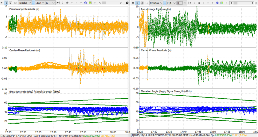
As you can see, the solution remains fixed when using only the GLONASS satellites for ambiguity resolution for a significant period of time and the residuals remain small. This is very encouraging.
To further verify things are working the way we think they are, lets look at the output traces for three runs, GPS AR only, GLONASS AR only, and GPS+GLONASS AR. I’ve added some trace output to list the satellite pairs used to make it easier to follow. RefSats are the reference satellites for each double difference pair, fixSats are the other satellite in each pair. N(0) is the float solution, N(1) is the fixed solution, and ratio is the AR ratio. All three outputs are for the same epoch but in three different runs. I picked a random epoch from the middle of the run.
Integer ambiguity resolution with GPS satellites (17:56:52)
3 resamb_LAMBDA : nx=98
3 ddmat: gps=1/1 glo=0/0
3 refSats= 10 10 10 10 10 10 10
3 fixSats= 13 15 18 20 21 22 29
3 N(0)= -1021543.012 -583342.043 -321520.024 -1128921.004 -351484.032 -1244853.988 -1342905.008
3 N(1)= -1021543.000 -583342.000 -321520.000 -1128921.000 -351484.000 -1244854.000 -1342905.000
3 N(2)= -1021543.000 -583342.000 -321520.000 -1128921.000 -351484.000 -1244854.000 -1342904.000
3 resamb : validation ok (nb=7 ratio=160.92 s=132.06/21251.08)
Integer ambiguity resolution with GLONASS satellites (17:56:52)
3 resamb_LAMBDA : nx=98
3 ddmat: gps=0/0 glo=1/1
3 refSats= 33 33 33 33 33
3 fixSats= 39 40 54 55 56
3 N(0)= -1572711.936 -785246.994 -1482008.966 -496531.985 151149.024
3 N(1)= -1572712.000 -785247.000 -1482009.000 -496532.000 151149.000
3 N(2)= -1572711.000 -785247.000 -1482008.000 -496532.000 151149.000
3 resamb : validation ok (nb=5 ratio=165.97 s=38.82/6443.06)
Integer ambiguity resolution with GPS and GLONASS satellites (17:56:52)
3 resamb_LAMBDA : nx=98
3 ddmat: gps=1/1 glo=1/1
3 refSats= 10 10 10 10 10 10 10 33 33 33 33 33
3 fixSats= 13 15 18 20 21 22 29 39 40 54 55 56
3 N(0)= -1021543.029 -583342.057 -321520.028 -1128921.020 -351484.040 -1244853.987 -1342905.016 -1572711.928 -785246.982 -1482008.949 -496531.972 151149.020
3 N(1)= -1021543.000 -583342.000 -321520.000 -1128921.000 -351484.000 -1244854.000 -1342905.000 -1572712.000 -785247.000 -1482009.000 -496532.000 151149.000
3 N(2)= -1021543.000 -583342.000 -321520.000 -1128921.000 -351484.000 -1244854.000 -1342905.000 -1572712.000 -785247.000 -1482008.000 -496532.000 151149.000
3 resamb : validation ok (nb=12 ratio=53.40 s=473.13/25263.69)
Everything looks as we would expect, so again that is encouraging.
Next I made a comparison using my four standard metrics for four solutions using different AR settings. The first is no AR, the second is GPS AR, the third is GLONASS AR, and the fourth is GPS AR+GLONASS AR. The plot is below, the x-axis is the four cases.

All looks good except that there is a small increase in the std(dist) metric for GLONASS AR which is measuring position error in the solution. This is not surprising and probably would be concerning if it were not so. The code has made a single guess at the inter-channel biases and so we would not expect to get them precisely correct. Any error in our inter-channel bias estimates will translate directly into error in the fixed solutions. If we want to improve the accuracy of the GLONASS fixed solutions we will need to improve the estimates of the inter-channel biases. This should not be difficult if we iterate the estimations over multiple epochs. Even without improved accuracy, we should still get increased robustness from having more satellites to use for the fixed solution. Note the increase from 8 to 13 satellites used on average for the fixed solution in the bottom right plot. Having more satellites available for the fixed solution should improve our ability to stay locked. To take advantage of this, however, we may need to exclude individual satellites from being used for ambiguity resolution or break the satellites into multiple sets since with the current algorithm a single bad satellite can prevent getting a fix.
Anybody have experience with using this sort of approach to estimate the inter-channel biases? Any obvious pitfalls I’m missing? Any other thoughts?
This is still just an experiment, not meant to be a functional feature yet, but I’ve posted the code to my Github repository in the exp1 branch in case anyone else would like to play with these options. The config file in the exp1\data\demo1 folder is setup to run with these two features both enabled.

Dear Tim,
if I understand it correctly – the inter-channel bias problem of GLONASS in RTKLIB is only a matter of a missing SW feature in the code? Sorry I havent read all the way through (tough post 🙂 but will there be something like a receiver (or antenna) callibration needed for RTKLIB to work?
LikeLike
Hi Kozuch. Adding the inter-channel biases to the set of unknowns increases the difficulty of the problem, so I would describe it as more than just a missing SW feature. I see that Swift just added the capability to their code for handling GLONASS AR for unmatched receivers but it does require having the IC bias calibration values for the other receiver, something that is not always available for low cost receivers.
LikeLike
Yes Swift’s Piksi Multi RTCM Input specs says that “In order to use Glonass for RTK positioning, either message 1033 or 1230 is required. Message 1230 is used in priority, but if unavailable the receiver will use the message 1033 to determine hardware biases necessary for GLONASS RTK.” I just checked that my nearby (European) CORS station outputs both 1033 and 1230, but in RTCM 3.2 while Piksi accepts 3.1 – do you think it will work this way?
1033 – Receiver and Antenna Descriptors (firmware v1.4 and newer)
1230 – GLONASS L1 and L2 Code-Phase Biases (firmware v1.4 and newer)
Source:
https://support.swiftnav.com/customer/en/portal/articles/2801480-piksi-multi
LikeLike
Do I understand correctly that RTKLIB can not handle the GLONASS bias messages (1033 or 1230)?
LikeLike
Hi Kozuch. RTKLIB does not support the 1230 message at all and has only partial support for the 1033 message which does not include the GLONASS biases.
LikeLike
Dear Tim,
what is the current status of the GLONASS AR in your latest (public) demo5 code? A guy over at Emlid forums says there is and “AutoCal” working already. You do negate a working GL AR for non-matching receivers in your latest post though so I am a bit confused.
Source:
https://community.emlid.com/t/glonass-ambiguity-resolution/9256/8?u=kozuch
LikeLike
Hi Kozuch. I have not had much luck with the AutoCal feature for GLONASS AR in RTKLIB in the past but have not tried it recently. I did add an extension to “fix-and-hold” in the demo5 code that will null the biases but it will only be enabled after the GPS ambiguities are resolved so is not an ideal solution. I almost always use matched receivers in my testing so this is not something I have tested very extensively. By the way, it looks like the guy on the Emlid forum replied again and said that he was using matched receivers so AutoCal would be unnecessary in that case.
LikeLike
this post might be useful
https://www.blackdotgnss.com/2018/03/05/glonass-rtk-with-low-cost-receivers/
LikeLike
Hi Ioa. Yes, there is some excellent information on the BlackDotGNSS blog, especially for those interested in the more theoretical aspects of GNSS. I include it in the list of recommended blogs on my “Resources” page.
LikeLike
Sorry, on further thought the roundabout idea does not confirm a true fix, there could still be an offset involved due to an incorrect fix yet still giving a true circle.
LikeLike
This looks very encouraging work.
Do you have any explanation for the low median AR result in case 4. Surely one would expect it to increase over case 2 or 3 or at least not worse?
Is it just a statistical problem, ie if it was repeated would the median AR be better?
LikeLike
Hi AR. It’s a good question. There’s a few things going on but the biggest problem I think is that it really did not make sense for me to summarize all the AR ratios into a single median. The AR ratio is not a direct measurement of the quality of the solution but rather a rough measure of how close the solution is to a set of integers. Initially it is a reasonable way to indirectly estimate the quality of the solution but as soon as the solution modifies the bias states to intentionally make them closer to integers (as do both the original fix-and-hold and the new version) this is no longer true and we are just measuring how close the solution moved the states to integers. For the original fix-and-hold, this continues to be the case as it continues to adjust the states. In my modified version, the adjustment only occurs once, so after that adjustment, the change in the AR ratio becomes more of an indication of how well we are tracking the solution. The median AR ratio for each of these three conditions by itself is probably meaningful, but the result of combining all three is not.
Another thing to realize about the AR ratio is that it is dominated by the worst satellite in the group which makes it difficult to compare AR ratios between two cases with different number of satellites. For example think of a very simple example where three satellite biases were perfect integers and a fourth had a fraction of 0.5. The AR ratio would be 1.0 because there are two equally likely solutions, the first three integers combined with either of the two integers closest to the fourth. If we then added six more satellites all with perfect integer biases, the AR ratio would remain at 1.0 since there are still two equally likely solutions. To take advantage of the additional confidence provided by the extra satellites we need a way to throw out the one bad satellite. For this reason, adding more satellites to the solution will often lower the AR ratio, not increase it, because the worst satellite in a larger group will tend to be worse than the worst satellite in a smaller group, even when the means are equal.
For these reasons the AR ratio would probably not be one of my choices for metrics if I was making it today, rather than back when I first started.
LikeLike
OK thanks, Its good to see someone well versed in the detailed mechanics of RTK doing some experimental work on RTKLIB software. I am merely a user with only relatively surface deep knowledge. However over many years I have noticed several shortcomings in RTKLIB. Good that it is it still falls short of a bomb proof application.
Lack of reliable fix and recovering from it being just one. Thus your idea of fix and hold until something much better comes along rather than fix forever sounds good.
Also when losing a float solution ( through trees. buildings etc) the single solution is wildly inaccurate ie a huge jump occurs which is much more than you would expect from a single solution with SBAS enabled ( which it is ) . This artifact arguably makes the RTK less accurate in this situation than a simple single solution with SBAS would be, ie that obtainable directly from the inbuilt solution from say a ublox M8T without using RTKlib.
Another major bug seem to be in the raw to RTCM3 conversion (in say STRsvr) or its implementation within RTKnavi. leading to relatively large transients occuring that do not occur when using pure raw data transmission between base and rover.
Coming back to the bias calibration for Glonass and AR on/ off options, I note that on closer look RTKnavi ( both 2.4.2 p11 and 2.4.3 b8+ ) has another option under Glonass AR:- Auto Cal!
This is documented in the manual but I have not used it to date nor indeed on Googling it can see anyone else has experimented with or mentioned it. I wonder if you have noticed it in the code and how it compares to your methods? BTW I like your idea of comments in the code it makes things much clearer .
PS I like your method of base and rover on the same vehicle in order to verify the validity of the fix purely by observing the circle or deviation from it. Do you choose normal base-rover kinematic, or moving base mode for that. if the former what base position do you put? If the latter I just get the absolute position for one of the two plus the baseline length and angle. Do you just postprocess the baseline length and angle to draw your circle? To test out normal base rover setup you could have a fixed base and put the rover on a childs roundabout or mockup of one, something I have thought about before, but never implemented. I suppose with a more mobile one ( on a pickup?) you could move it from place to place to examine effects of tree shading etc. stopping every now and then to get the circling effect , and to see how it recovers from a loss of fix en route.
Regards
Anthony
LikeLike
Hi Anthony. I have also noticed that the RTKLIB single solution can be quite poor and much worse than the receiver solution . At one point I wrote some code to pass the receiver solution onto RTKLIB thinking it could use it as an additional or alternative input to the kalman filter but never pursued it beyond that point. This is just a workaround though, it would be much better to fix the RTKLIB single solution.
I am curious to hear more about your problems with STRSVR. I have seen your comments about them elsewhere but have not tried to duplicate them. I was recently tracking down a problem I saw in my data with many half cycle errors shortly after a cycle slip and found that STRSVR is ignoring one of the status bits, which although undocumented, must be the half cycle valid bit. Could this possibly be related to what you are seeing?
I have tried the GLONASS AR autocal option but have not had any luck with it. If it worked it would be superior to my method since it is more of a true estimate and does not rely on fix-and-hold. It adds a state to the kalman filter to estimate a single offset term for all satellites that is proportional to the difference in carrier frequencies.
I did not discover moving-base mode until fairly recently so all my posts are based on normal base-rover kinematics. I set the input configuration file to use the position in the observation file header for the base position. If you are interested only in relative position between the two receivers then the base position does not need to be exact, just reasonably close. I have since found that moving-base does give a slightly more accurate answer. Looking through the code, however, I found that the most significant difference in the solution algorithm when running moving-base is that it adds two additional iterations of the kalman filter for each epoch. According to the RTKLIB user manual, additional iterations are recommended for short baselines, so I think this is just recognition that moving-base configurations tend to have short baselines. I find adding two iterations to the kinematic solution (using the “niter” input parameter) gives a virtually identical solution to moving-base. I am sure you are aware, but I should note for anyone else using moving-base solutions, that the baseline input parameter must be set to something greater than zero or the additional iterations will be skipped.
Since we are looking only at relative distances between the two receivers, I believe the roundabout on the back of a pickup is effectively identical to just mounting the receivers directly to the pickup. Whether you park the pickup and spin the roundabout or drive in a tight circle, the relative motion between the two receivers will be the same. The common motion of the two in the latter case won’t affect the distance or orientation between them and will be insignificant relative to the distances to the satellites.
Regarding your last point about confirming true fixes on the roundabout, remember that all kinematic solutions are relative distances and orientations between the two receivers, any absolute results are derived by assuming a known location for the base. Therefore, if the solution is a perfect circle with a radius equal to the distance between the rovers, then this is indistinguishable from any other correct solution. I suspect that the only way there can be an offset if the solution is correct is if both receivers slip the same number of cycles on the same satellite, and hence the offsets cancel. Although we may not be able to detect this scenario, it should be extremely unlikely, and may not matter anyways since it doesn’t affect the answer.
Again, I want to emphasize that I am learning all this as I go and am still fairly new to RTK so please accept everything above with some skepticism. My answers just represent my best interpretation of what I have learned so far and it is quite possible there are errors or over-simplifications in all of my answers.
LikeLike
Hey I am not quite sure if I just can ask here something. I am newbie and I have a lack of the basic understanding already.
SO first of all let me explain what I would like to do: I would like to buy an Intel nuc board (e.g:NUC5i5MYBE ) and run Ubuntu 14.04 on it. Then I would like to install ROS on it. Thereby I would like to install the RTKLIB package on ROS. Then I would like to connect this INTEL Nuc board with my quadrocopter controller by a serial port. The quadrocopter controller is connected to a u-blox: Neo M8T receiver (by UART?, USB?). The quadrocopter is the rover. As a base station(which is fixed) I want to use just another NEO M8T reciever. Note that the quadrocopter is flying (not fixed) in a range of max. 2km away from the fixed base station.
What I would like to accomplish:
I want to be able to determine the baseline with an accuracy about 2cm. RTK – Relative Positioining, short baseline EKF solution for solving the integer ambiguity problem as RTKLIB implemnts it.
My Questions:
(1) What will be a good way to connect the NEO M8T receiver to the intel nuc board? (By UART?, USB?, SPI; DDC port).
(2) Does anyone have some experienc with baud rates that RTKLIB (using the ROS package) needs to calculate in real-time a centimiter-level precise baseline. I mean what rate of bits have to be send over the UART or USB port between the receiver and the rover in what time to achieve such an accuracy. Is the NEO M8T a usefull receiver to accomplish this goal?
(3) What is a good way to connect the base station with the rover. What kind of Data Link would you suggest I should use? One example would be using another PC as a base station, and running a STRSVR Server on this base station PC. This base station is connected by UART to the base station ubox receiver. The connection in this example is using a WIFI connection. (Note in this case the intel nuc of course must have a wifi card so that it can receive a wifi(2.4GHZ) signal.
(5) Would you advise to use another frequency instead of WIFI? Is WIFI enough or too much to accomplish the Baud exchange rates needed for high accurate positioing in real time?
(4) Would you advise to buy a UBlox Kit like the C94-M8P? To do the job?
I would be very delighted to hear your suggestions here. Hope you can help me.
A Link:
https://www.u-blox.com/de/product/neolea-m8t
LikeLike
Hello
my name is Xavier and I write from Italy.
Time use RTKLIB with receivers Ublox M8N.
I also have 3 NV08C-CSM.
I followed your posts and I congratulate you so much capacity.
I also want to try it myself to resolve the ambiguity of the Glonass, but are not good at fill.
I can get the bin file already modified?
Thank you
LikeLike
Hi Markus. I’m afraid I don’t know much about the hardware you are asking about. I have seen quite a bit of drone related GPS info on the forums at http://diydrones.com/. Have you looked there? Based on some of the that discussion, I believe reliably getting the kind of accuracy you are looking for in the drone environment may be quite challenging but I encourage you to give it a shot as long as your not underestimating the difficulty.
LikeLike